

Automated Bore Welding Parameters: How to Set Up and Fine-Tune a Weld

What if a setting improves one part of a bore weld but makes the bead profile worse somewhere else? That’s the challenge with automated bore welding parameters. Amperage, voltage, travel speed, and step work together, so a setting that suits one machine or repair may not suit another.
If you’re unsure which control to adjust, or inconsistent profiles are leading to extra machining, don’t copy a setting and hope it fits. Start with a sound baseline, change one variable at a time where the procedure allows, and assess the result as a whole. The right setup depends on the equipment, material, joint preparation, and applicable welding procedure.
This guide explains how the main controls influence heat input, bead shape, and placement. It also gives you a repeatable process for establishing and validating a parameter set, plus a way to troubleshoot variation without changing several settings at once. Use machine documentation and the applicable procedure to guide your setup. Treat example settings as starting points, not universal recipes.
Table of Contents
What automated bore welding parameters control in a repair
Automated bore welding parameters are the controllable settings that affect arc behavior, bead placement, and the amount of weld metal deposited as the welding head travels through a bore. Depending on the system and process, they may include amperage, voltage, wire feed, travel speed, and the step or increment between passes. Together, these controls shape how weld metal builds across the damaged surface.
The deposited metal is usually a machining allowance, not the finished bore. The weld needs to build an even layer that can be machined to the required dimensions. Too little or uneven buildup can leave areas short of material, while an inconsistent profile may require more corrective machining or rework. Parameter control helps make deposition repeatable, but it doesn’t replace proper preparation, machine setup, or post-weld machining.
Keep these tasks distinct. Machine setup positions and secures the equipment. Workpiece preparation establishes the surface and joint condition. Parameter selection controls the welding process, and machining brings the repaired bore to size. Because each step affects the next, choose parameters with the equipment, base material, wire, bore geometry, and applicable welding procedure in mind. For foundational context on the process, see Arc welding principles.
What makes bore welding parameter-sensitive?
A bore limits access to the work area. The welding head follows a controlled path inside the opening, laying successive passes over a curved surface rather than across an open plate. Pass spacing and overlap matter: an appropriate pattern can build an even deposit for machining, while poor placement can leave ridges or gaps. The bore’s orientation, clearance, and existing condition also affect the setup.
For example, an out-of-round bore or one with uneven wear may present different surface conditions around its circumference. Access can also vary with bore depth and surrounding structure. These details don’t prescribe a setting by themselves, but they explain why operators need to assess the actual repair instead of assuming every bore will respond the same way.
Why one published setting is not a universal recipe
Published parameter examples can illustrate how settings relate, but their values apply to the equipment, consumables, material, and repair conditions for which they were developed. A number without that context is incomplete. Use examples as references only when the application matches, and rely on the relevant machine documentation and procedure when setting up a specific job.
Machine design, consumables, material, bore dimensions, orientation, and the applicable procedure all affect whether a setting transfers. A parameter set is valid only in its stated application context. Assess the resulting deposit against the repair’s machining needs, rather than treating a published setting as a default for every bore welding system.
How amperage, voltage, travel speed, and step work together
Each control affects the weld differently. Amperage is the welding current and influences arc energy and how the wire melts. Voltage influences the arc’s electrical characteristics, including arc length and bead shape. These effects are connected, not interchangeable: changing one setting can alter arc behavior even if the other stays the same. Controls and their relationships vary by equipment, so use the machine documentation and applicable procedure as your reference. For general context, TWI Global explains the fundamentals of welding.
Wire feed speed and travel speed also need to be considered together. Wire feed controls how quickly filler wire enters the arc, while travel speed is how quickly the welding head moves along its path. Depending on the system, wire feed may be linked to current or controlled separately. If the head travels faster while deposition stays the same, the amount of weld metal laid along each section can change. Check how your machine coordinates these controls instead of assuming the same relationship across systems.
How electrical and motion controls affect the bead
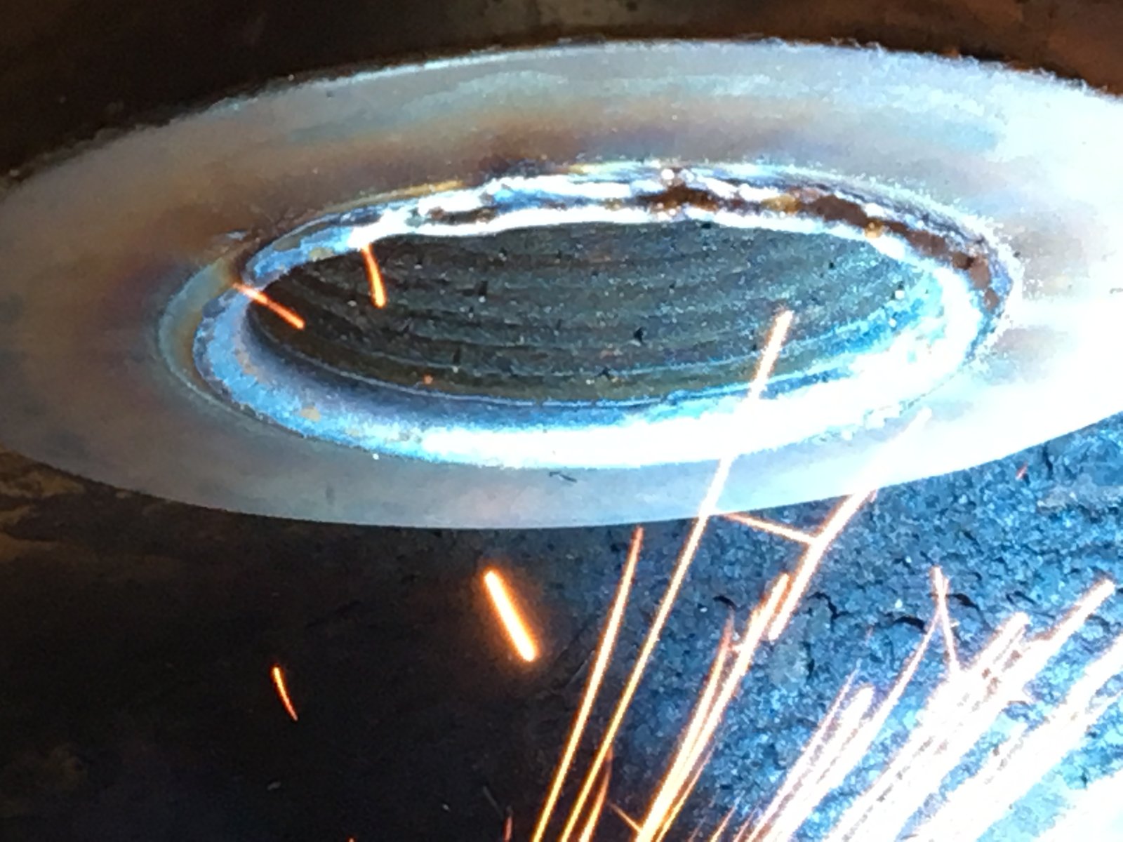
During a test, observe the arc and the bead together. Note whether the deposit is narrow or broad, smooth or irregular, and whether its profile stays consistent along the path. Heat input is influenced by electrical settings and travel speed together, not by a single dial. Make adjustments only within equipment and procedure guidance, then inspect the result before choosing the next change.
Use these relationships as observation points, not universal correction rules:
Amperage: Influences current and wire melting. Observe bead size and consistency.
Voltage: Influences arc characteristics and bead shape. Watch for changes in arc stability and profile.
Wire feed speed: Controls wire delivery, with its relationship to current depending on the system. Check whether deposition remains consistent.
Travel speed: Sets the rate of movement along the bore. Observe how the deposit is distributed along the path.
Step or overlap: Sets pass spacing. Inspect whether adjacent passes cover evenly and create a consistent profile.
What step and overlap reveal about coverage
Step describes the spacing between adjacent weld passes, although the machine documentation determines exactly how the setting is defined or measured. In a specific machine’s terminology, step is the programmed spacing between successive weld passes. Appropriate spacing lets passes overlap enough to cover the bore surface and build a usable deposit profile. Too much or too little overlap may appear as gaps, ridges, or uneven buildup.
Those signs call for diagnosis, not an automatic step change. Check the pass pattern alongside the bead, machine travel, wire delivery, and workpiece condition. Record what you observe, then adjust one variable at a time where equipment guidance and the procedure allow. This helps distinguish a spacing issue from a problem elsewhere in the process.
For teams developing more consistent operator practices, bore welding training can help build a repeatable setup and inspection routine.
Which job conditions should determine your parameter baseline?
Set a baseline for the repair in front of you, not for an abstract “typical bore.” Before choosing automated bore welding parameters, identify the equipment and job conditions that affect the process. A chart or example can inform your thinking, but it can’t replace the applicable machine documentation or welding procedure.
Build a job-specific starting point
Begin with the equipment instructions and applicable procedure. Then record the job details that help you judge whether a reference setting fits. RSI’s overview of key welding parameters provides broader context, but the machine documentation and procedure remain the working references for your setup.
Machine: Record the machine and relevant configuration. Controls and parameter ranges vary by equipment.
Material: Identify the workpiece material and any details specified in the procedure.
Wire: Note the wire type and size used for the test.
Bore geometry: Record bore dimensions and condition, including wear or irregularities that may affect the pass path.
Orientation: Note the machine and workpiece orientation, along with relevant access or setup conditions.
Separate confirmed guidance from operator observations. Label machine-manual and procedure requirements clearly, and identify shop notes or informal examples as observations, not approved settings. A published chart doesn’t automatically apply to every bore welder. Its values are useful only when its equipment, consumables, material, and application context match the job.
Use observable evidence to assess the baseline
A starting point is useful only if you can connect it to the result. During a controlled test, assess pass placement, continuity, coverage, and whether the deposit leaves enough allowance for machining. Record where the profile changes along the bore, along with relevant setup conditions. Specific observations are more useful than a general note such as “the bead looked good.”
A comparison table makes the results easier to assess. Use one row for each test, with the settings beside the observed weld profile. Include the machine, material, wire, bore details, orientation, parameter values, and inspection notes. Record anything that changes between tests. This gives the team a traceable basis for comparison instead of relying on memory or copying a setting without its context.
Compare parameter records with the resulting weld profile. This shows whether a setting produced the coverage and machining allowance the job needed. It also makes troubleshooting more disciplined: review what changed and what the weld looked like before selecting the next test. Keep reference values clearly identified as examples unless their application matches your equipment and repair.
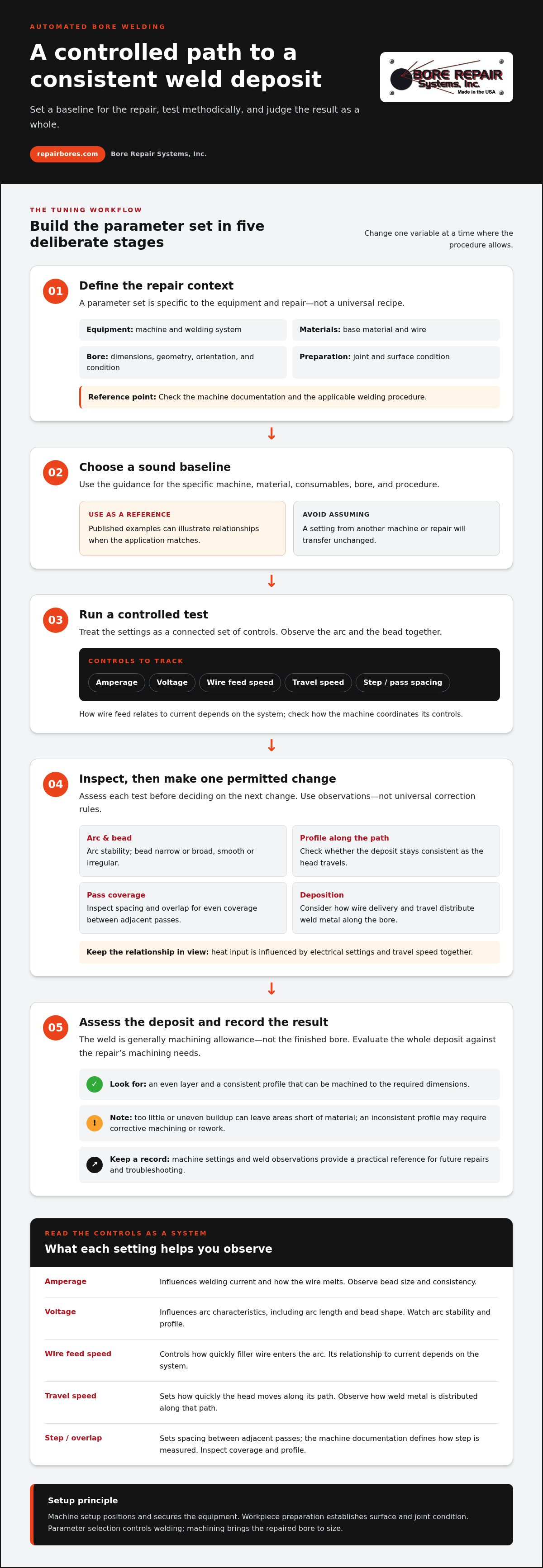
How to tune automated bore welding parameters methodically
Tune the process through a controlled loop, not a series of simultaneous guesses. Keep the machine instructions and applicable welding procedure in front of you, since they set the boundaries for the test. Within those boundaries, change one variable at a time where the equipment and procedure allow. This makes it easier to connect an adjustment to the result.
A controlled test-and-adjust sequence
Use the same basic sequence for each test. Consistent setup conditions make the results easier to interpret and give the team a useful record for future repairs.
Review the procedure. Confirm the required process guidance and machine-specific limits before selecting settings. Don’t substitute an informal example for approved instructions.
Check the setup. Confirm the machine is installed and operating as directed. Verify the workpiece condition, wire and other consumables, and applicable safety controls before welding.
Establish a baseline. Record the initial settings alongside the machine configuration, material, wire, bore condition, and orientation. Note setup details that could affect the test.
Run a controlled test. Apply the baseline under the documented conditions. Avoid changing other setup factors during the test unless safety or equipment guidance requires it.
Inspect the result. Record pass placement, continuity, coverage, and deposit profile. Compare the material built up with the allowance needed for machining.
Adjust and record. If the result needs improvement, make one permitted adjustment, document it, and repeat under comparable conditions. Save the updated setting with its inspection notes.
Troubleshoot inconsistency without guesswork
An uneven bead, inconsistent coverage, or a change in profile is a clue, not proof that a particular setting is wrong. Before changing controls, check for variation in machine setup, workpiece condition, consumables, and machine operation. Any of these can affect the weld and make a parameter adjustment misleading.
Compare the weld with the job’s intended machining allowance. Check whether the deposit is continuous and whether its profile leaves the material needed for machining, rather than judging appearance alone. If the cause remains unclear, return to the documented baseline and review what changed since the last consistent result. Follow machine guidance and procedure requirements; don’t make a numeric correction based on a visual symptom alone.
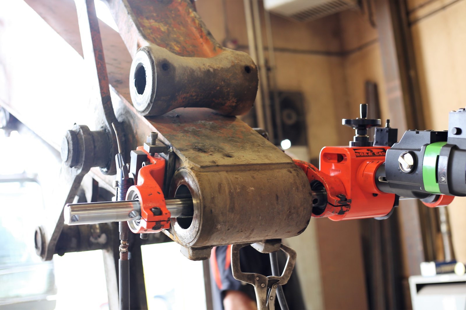
For a visual reference to equipment operation, review the bore welding and portable boring videos. Use them to support your understanding of the process, not as a replacement for machine instructions or a qualified welding procedure.
A disciplined record turns each test into evidence instead of guesswork. Bore Repair Systems provides practical bore welding training to help operators build consistency and follow a repeatable process.
How equipment and operator training support repeatable bore welding
Repeatable results depend on more than a saved setting. The machine needs to be set up consistently, the operator needs to understand the process, and the result needs to be checked against the repair’s requirements. If setup varies between shifts, the same parameter values may not produce comparable welds. Clear instructions and shared practices help make adjustments deliberate rather than dependent on individual habits.
Make parameter knowledge repeatable across operators
Use the same terms for controls and observations across the team. A note such as “step changed” is useful only if everyone understands which machine setting it describes. Pair setup notes with what the operator observed, such as pass coverage, continuity, or profile. That gives the next operator more than a list of numbers to copy.
A useful job record can capture:
The machine and its relevant setup or configuration
Workpiece material, bore condition, and orientation
Wire and other consumables used
Parameter values and any changes made during testing
Operating conditions, setup observations, and inspection findings
The resulting weld profile and whether it left suitable material for machining
Training makes these records more useful by connecting parameter choices to visible outcomes. Operators can learn to recognize changes, describe them consistently, and follow a controlled process when investigating variation. Bore welding and line boring training can build practical operating knowledge across a team, including a stronger understanding of advanced bore welding techniques.
Choose equipment and learning support for the work
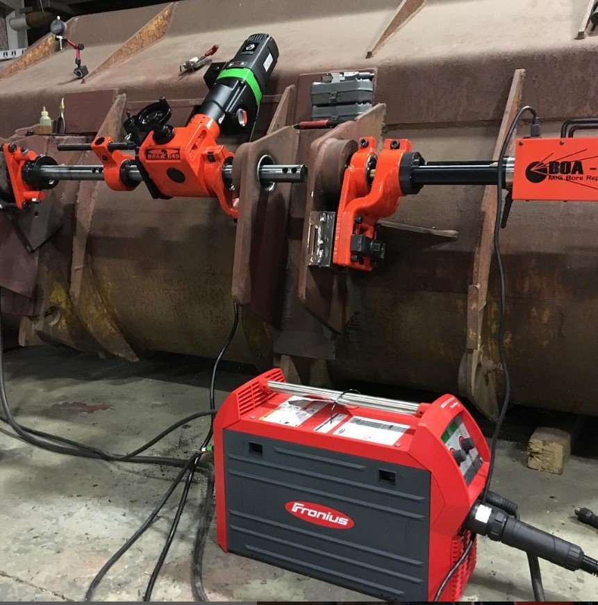
Parameter control starts with equipment suited to the repair and operated according to its instructions. Bore Repair Systems manufactures and sells bore welders, line boring machines, and related bore repair equipment, along with training for bore repair operations. Understanding how equipment is intended to function helps operators interpret its controls and apply the relevant machine-specific guidance. The bore welder overview provides context on the role of this equipment in bore repair.
Build a repeatable routine around the machine: follow setup instructions, use the applicable welding procedure, document test conditions, and compare each result with the intended machining allowance. Keep the record with the job so future operators can see both which settings were used and how the weld performed. Connecting equipment, process knowledge, and validation supports more consistent decisions.
For teams developing operator skills, Bore Repair Systems provides bore welding and line boring training. Equipment and training information is available through Bore Repair Systems.
Make your next setup easier to repeat
Turn each validated repair into a clearer starting point for the next one. Keep useful observations with the job record and use them to guide future tests, without treating past settings as automatic answers. This builds a practical reference grounded in your equipment, work conditions, and inspection results.
That’s the value of treating automated bore welding parameters as part of a documented process, not as isolated numbers on a control panel. Keep refining the method, follow the applicable machine guidance and welding procedure, and make sure operators know how to assess the result.
To build a more consistent setup or develop operator skills, contact Bore Repair Systems about bore welding equipment or training. Give your crew a process they can understand, validate, and use with confidence.
Frequently Asked Questions
What are the main parameters used in automated bore welding?
The main controls commonly include amperage, voltage, wire feed speed, travel speed, and step or pass spacing. Together, they influence arc behavior, deposition, and where each pass lands. A machine may coordinate some controls or present them differently, so read its instructions before interpreting a displayed value. For a useful test record, write down control names exactly as shown on the machine, along with the observed weld result.
How does step affect bead placement in automated bore welding?
Step sets how far the welding path advances between adjacent passes, affecting how much one bead overlaps the next. If coverage appears inconsistent near a transition or around part of the bore, inspect the actual pass pattern before changing the setting. Also consider whether the weld head followed the intended path. A visible ridge or gap is a reason to investigate, not proof that step alone is the cause.
Can the same automated bore welding settings be used for different materials?
Not automatically. Different workpiece materials and wire combinations can respond differently to the welding process, so don’t assume a setting used on one repair is suitable for another. Confirm material and consumable requirements in the applicable procedure and equipment instructions. For example, a change in wire type can make a previously recorded baseline unsuitable even if the bore dimensions and machine appear unchanged.
Is there a standard amperage setting for automated bore welding?
There isn’t one amperage value that applies to every bore welder and repair. The appropriate setting depends on the equipment, process, material, wire, and procedure. Don’t use a number from an example chart as a universal instruction. Start with the machine guidance and applicable procedure, then document the setting and resulting weld profile. If the result differs from expectations, investigate the setup before making an adjustment.
How do you know whether an automated bore weld is ready for machining?
Use the applicable procedure and inspection requirements to determine whether the weld can proceed to machining. Check the deposit against the specified acceptance criteria and confirm that enough material is available for the planned finished dimensions. A smooth-looking surface alone doesn’t establish suitability. If the deposited profile varies around the bore, assess the affected areas and resolve concerns before machining removes the available material.
What causes an inconsistent bead during automated bore welding?
Inconsistency can result from changing setup conditions, an irregular workpiece surface, consumable variation, machine operation, or parameter selection. Look at where the variation occurs: a change at the same point in each pass may indicate a repeatable setup or path issue, while broader variation may have another cause. Compare the affected weld with the job record, then investigate before changing settings.
Does automated bore welding require operator training?
Training helps operators use equipment correctly, follow applicable procedures, and interpret what the weld is showing. Whether formal training is required depends on the job’s governing procedure and requirements, so don’t assume a universal rule. Practical instruction can help teams use consistent terminology, recognize changes in bead profile, and document useful observations. Bore Repair Systems provides training for line boring and bore welding operations.
Comments