

How to Prevent Bore Ovality: A Precision Repair Guide

A bore can measure correctly in one direction and still reject a pin because it’s out of round. Knowing how to prevent bore ovality starts with looking beyond the final diameter: clamping, machine alignment, weld heat, and measurement can all affect the result.
If readings change with the measuring direction or setup, review the process before removing more material. A rushed correction can make the bore harder to bring back within tolerance. This guide explains how to identify likely causes of ovality and control each repair step, from initial inspection through final checks.
You’ll learn how to take repeatable measurements, secure and align the setup, manage heat during bore welding, and machine the bore in a controlled sequence. We’ll also cover how bore repair equipment and operator training support consistent results. The goal is a repair that fits the mating component and passes inspection without avoidable rework.
Table of Contents
What Bore Ovality Means in Heavy Equipment Repair, and Why It Matters
A repaired pin bore needs more than the correct nominal diameter. Its shape around the circumference matters too. A bore can measure within its diameter range at one point yet still have a tight direction and a loose direction, affecting how a pin seats and moves under load.
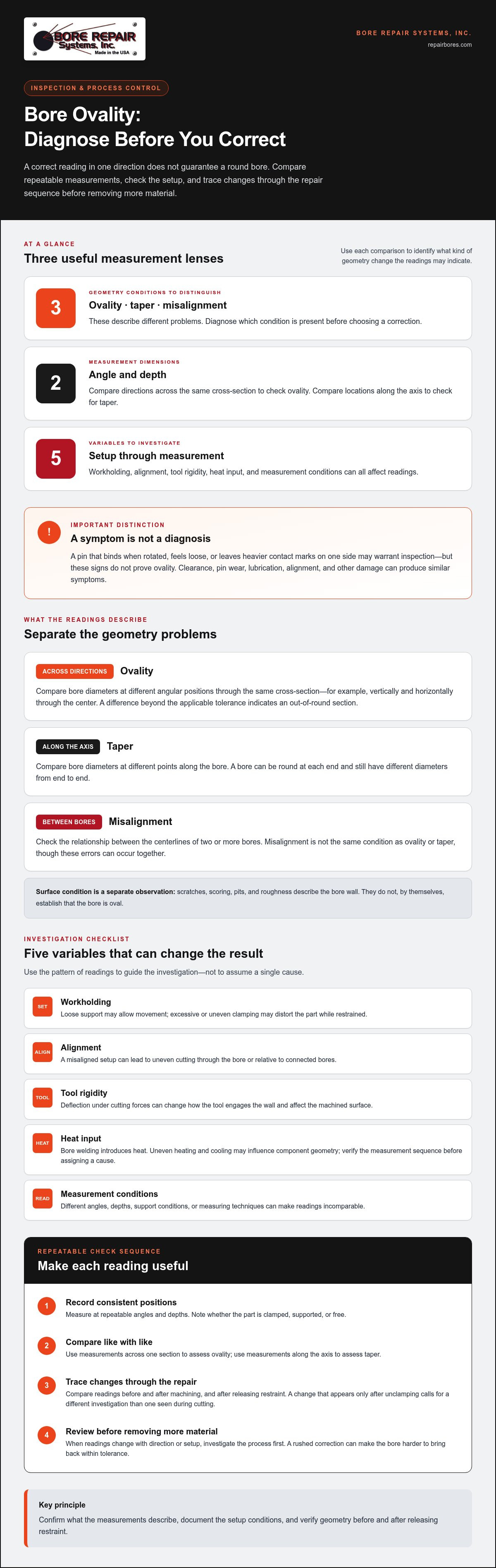
Bore ovality is the difference between bore diameters measured across different directions at the same cross-section. For example, compare a diameter measured vertically with one measured horizontally through the bore’s center. If those readings differ beyond the applicable tolerance, the cross-section is out of round. A bore is the cylindrical opening that receives or guides a component; Understanding Engine Bore provides a basic engine-context reference for the term.
How bore ovality shows up in service
A pin may enter smoothly in one orientation but bind or feel loose when rotated. Contact marks may also appear heavier on one side, suggesting the pin and bore aren’t sharing contact evenly. These symptoms warrant inspection, but they don’t prove ovality on their own. Clearance, pin wear, lubrication, alignment, and other damage can produce similar signs.
Localized wear can change the bore wall unevenly. Repeated loading in a particular direction may wear or deform one area more than another, so measurements around the same cross-section can vary. That variation matters because uneven contact can concentrate load, accelerate wear, and affect the fit of the mating component. Compare readings at repeatable positions before deciding whether the repair needs machining, material restoration, or a different correction.
Ovality, taper, and misalignment are different problems
Measure ovality across different angular positions at the same depth. Measure taper by comparing bore diameters at different points along its axis. A bore may be round at each end but have different diameters from end to end. Misalignment is different: it concerns the relationship between the centerlines of two or more bores. These errors can occur together, but each describes a separate geometric condition and needs to be diagnosed before correction.
Don’t confuse these shape errors with general surface irregularity. Scratches, scoring, pits, or roughness describe conditions on the bore wall. They may affect contact and inspection, but they don’t by themselves establish that the bore is oval. A smooth surface can still be out of round, just as a round bore can have local surface damage.
Keep the measurement question precise: are you comparing directions across one section, locations along the axis, or the alignment between bores? That distinction helps turn inconsistent pin fit into useful inspection evidence. It also gives the repair team a sound basis for selecting the next check, rather than removing material based on a symptom alone. For visual context on line boring and bore welding setups, explore line boring and bore welding examples. Understanding the geometry is the first step in how to prevent bore ovality during repair.
What Causes Bore Ovality During Machining and Repair?
Ovality can develop during machining, become more noticeable after a part is unclamped, or appear because measurement conditions changed. Workholding, alignment, tool rigidity, heat input, material response, and measurement technique can all affect the readings. A single high or low measurement is a clue, not a diagnosis. Compare readings taken under consistent conditions and note the setup before changing cutting or welding parameters.
Diagnose the cause before changing parameters. Otherwise, adjusting the process to compensate for one issue can introduce another problem or hide the original one.
Setup, alignment, and workholding effects
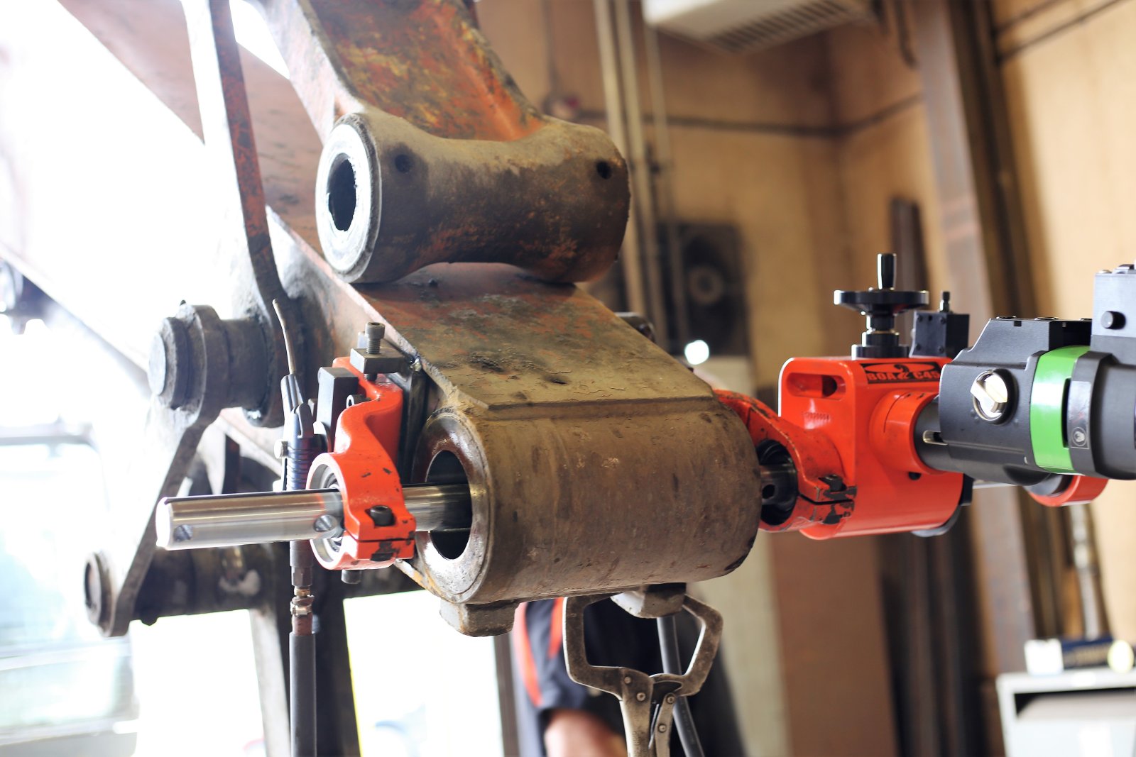
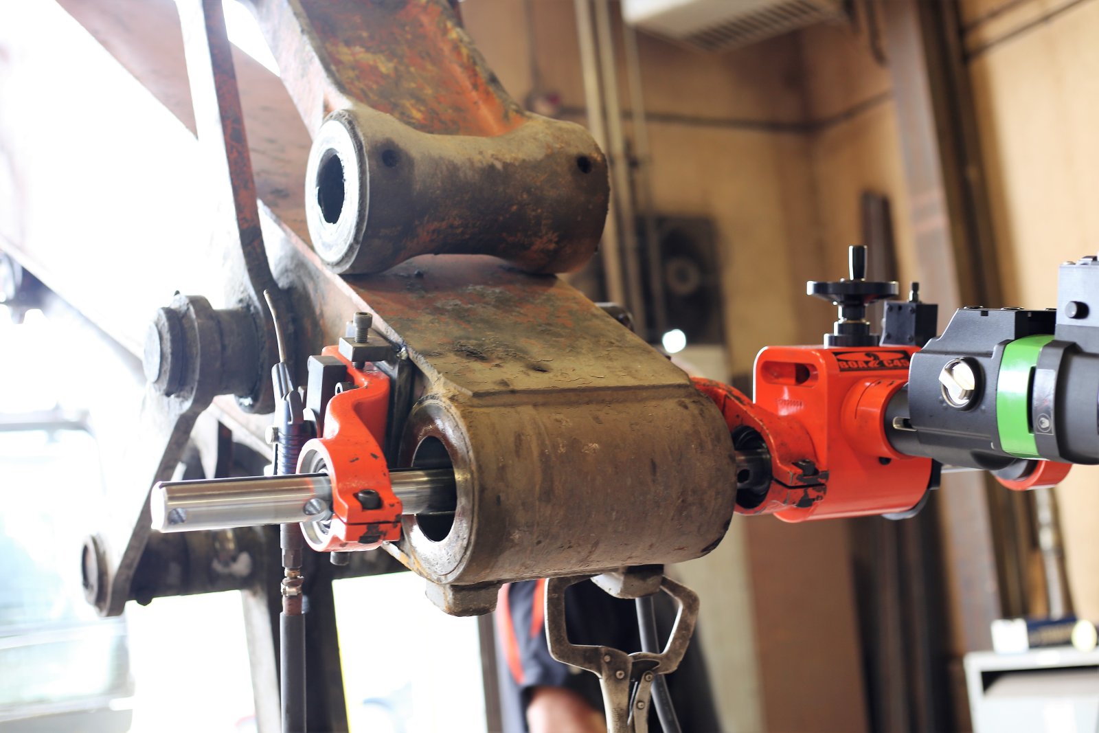
Unstable support or uneven clamping can let a component shift or distort while it’s being machined. Poor alignment can also make the tool cut inconsistently through the bore. Check that the component and boring equipment are supported securely and aligned before removing material. Record whether each measurement was taken with the part clamped, supported, or free, since restraint can affect the shape being measured.
Use the pattern of readings to guide the investigation, not to jump to a single cause. Common variables to check include:
Workholding: Loose support may allow movement; excessive or uneven clamping may distort the part while it’s restrained.
Alignment: A misaligned setup can cause uneven cutting along the bore or relative to connected bores.
Tool rigidity: Deflection under cutting forces can change how the tool engages the wall and affect the machined surface.
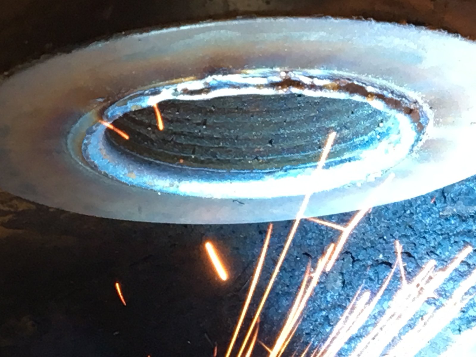
Heat input: Bore welding introduces heat. Uneven heating and cooling may influence component geometry.
Measurement conditions: Different angular positions, depths, support conditions, or measuring techniques can produce readings that aren’t directly comparable.
Heat, cutting forces, and material condition
Welding heat can cause local expansion, and the component may change shape as it cools. The effect depends on the part, so don’t assume that welding caused ovality just because readings changed afterward. Material response and residual stress may also contribute, but the measurement sequence should support that diagnosis before either is treated as the cause.
Cutting forces matter too. If the tool or support deflects under load, the cutter may remove material unevenly. Look for changes that track with machining, then compare them with readings taken before cutting and after releasing restraint. A geometry change that appears only after unclamping points to a different investigation than one that develops during the cut.
Separate the timeline: establish when the readings change, under what support condition, and at which positions. That gives the next inspection or setup adjustment a clear purpose and helps prevent blind corrections. Bore Repair Systems, Inc. sells bore repair equipment and provides line boring and bore welding training to support consistent setup and operation. Explore bore repair equipment and training.
How to Diagnose Bore Ovality Before Choosing a Correction
Start with a measurement pattern, not a single reading. A bore’s apparent shape can change with measurement direction, depth, restraint, or the point in the repair process. Record readings before machining, at planned inspection points during the work, and after releasing the component from its supports. This timeline helps distinguish a geometry issue from a setup-dependent change.
Build a repeatable measurement record
Use suitable measuring equipment, such as a bore gauge, with a measurement range and resolution appropriate to the required tolerance. Follow the instrument’s setup procedure and use the same method each time. Record enough detail for another operator to repeat the check:
Location: Identify the bore and the depth or axial position being measured.
Direction: Note the measurement angle, such as horizontal or vertical, and keep angular positions consistent.
Conditions: Record whether the component is clamped, supported, or free, and whether the reading was taken before, during, or after machining.
Equipment: Note the measuring tool and its calibration status, along with the reading and units.
Repeat each reading using the same contact and alignment technique. If successive readings at one position disagree, check the measuring method and instrument setup before interpreting the difference as a change in the bore. A written record is more useful than relying on memory or a single measurement.
Compare readings to isolate the likely source
Compare measurements across angular positions at one depth to assess roundness variation. Then compare readings at different depths to check for taper or other axial variation. Repeat the same comparisons while the component is restrained and after it’s unclamped. A change after release may indicate that restraint affects the measured shape, so don’t automatically attribute it to cutting.
Use the patterns as diagnostic clues, not as a substitute for the component drawing or inspection plan:
Interpret acceptance against the component specification and application requirements. There isn’t one universal ovality limit for every bore, pin fit, and duty cycle. Confirm which dimensions and form tolerances govern the repair before selecting a correction. A consistent measurement record makes it easier to decide how to prevent bore ovality from recurring by showing when and where the geometry changes.
How to Prevent Bore Ovality: A Repeatable Repair Workflow
Preventive control starts before the cutter touches the part. Inspect the component, establish its baseline geometry, stabilize the work, and confirm alignment before welding or machining begins. Then follow a consistent sequence of machining checks and final measurements. This makes it easier to spot changes early, while there’s still time to investigate rather than simply cut more material.
Use the component specification and the equipment manufacturer’s guidance to determine setup and process requirements. Don’t rely on a remembered setting from a different component or change multiple variables at once. A clear sequence supports repeatability and helps the operator connect any change in readings to the step where it occurred.
Before machining: establish a stable baseline
Clean the bore and the surfaces used for support or alignment before inspection. Dirt, weld spatter, burrs, or debris at a contact point can affect setup and readings. Record the bore’s existing geometry, the component’s restraint condition, and the alignment state. Confirm the work and machine are stable for the planned repair, then save the baseline measurements so later checks have a meaningful reference.
Move through the repair in order:
Inspect: Check the bore, surrounding material, and contact surfaces for damage or debris that could affect measurement or support.
Stabilize: Support and restrain the component consistently. Avoid changing the restraint method between checks unless the change is deliberate and documented.
Align: Verify the machine setup against the repair geometry before material removal. A sound baseline won’t help if the boring axis is incorrectly established.
Machine: Use the process and equipment settings appropriate to the component and operation. Keep technique consistent, and avoid unsupported adjustments when a reading changes.
Measure: Check geometry at planned stages, using the same locations and directions where possible. Don’t wait until the final inspection to discover that readings have shifted.
Document: Record measurements, restraint conditions, setup changes, and process checkpoints so the result can be reviewed and the method repeated.
During and after machining: control and verify
At each planned check, compare the new readings with the baseline and note whether the component remains restrained. If readings shift, pause and review the setup and measurement conditions before changing equipment settings. After machining, release the restraint and repeat the relevant measurements. This final check shows whether the geometry holds when the component is no longer clamped in the repair setup.
Equipment condition is part of process control. Follow the manufacturer’s inspection and maintenance guidance, and use a line boring machine maintenance guide to support consistent equipment checks. Bore Repair Systems, Inc. provides line boring and bore welding training to help operators build repeatable setup and operating habits. Learn about line boring and bore welding training. A disciplined workflow is the practical foundation for how to prevent bore ovality without relying on guesswork.
Choose Bore Repair Equipment and Training That Support Consistency
Equipment selection should follow the repair, not the other way around. Consider the component’s access, the scope of material restoration, the bore geometry to be machined, and the level of process control the job requires. A setup that works well for one component may not suit another. Match the equipment to the work, then follow its operating guidance and the component requirements.
Bore welders and line boring machines perform different jobs in the repair sequence. A bore welder can build material back onto a worn surface. A line boring machine then machines the bore toward its required geometry. Neither tool alone guarantees a particular result. Setup, equipment condition, process control, measurement, and operator skill all contribute to the outcome.
When bore welding and line boring work together
For a repair that requires material restoration, bore welding may precede machining. After the deposited material is ready for the next stage, line boring removes material in a controlled way to bring the bore toward its target size and alignment. The sequence depends on the repair scope and component requirements. For equipment fundamentals, the bore welder overview explains the role of this equipment.
Before choosing or setting up equipment, define what the repair must achieve. Check the component’s access and the geometry that needs correction. Then consider whether the process requires material buildup, machining, or both. Keep the inspection plan connected to the operation so measurements can show whether the setup is producing the intended result. Reliable equipment supports repeatable work, but it still needs to be applied correctly.
Build repeatable operator capability
Training helps operators develop consistent habits for alignment, setup, process operation, and measurement. Those habits matter because small differences in how a machine is mounted, how the component is restrained, or how readings are taken can make results harder to compare. Line boring and bore welding training can give teams a shared process to follow, helping them recognize setup issues and document work consistently.
Build that capability around the actual workflow. Operators should understand what to verify before machining, which conditions to keep consistent during the operation, and how to record checks. Visual demonstrations can also help reinforce equipment handling and process steps. Use the available bore repair videos as a visual learning resource alongside hands-on practice and equipment guidance.
Choosing suitable equipment and developing repeatable operator habits are practical parts of how to prevent bore ovality. Explore Bore Repair Systems, Inc.’s bore repair equipment and training.
Build Consistency Into Your Next Repair
Turn ovality control into a repeatable shop practice. Use each repair to strengthen the way your team prepares equipment, sets up the component, and confirms results. Clear work instructions and operator habits help keep the process consistent, even as repair conditions change.
Bore Repair Systems, Inc. manufactures bore welders and line boring machines, and provides training in line boring and bore welding operations. The right tools and practical operator knowledge can help your team approach each repair with greater process control.
Make your next step a focused review of the equipment and skills your repair workflow requires. Explore bore repair equipment and training with Bore Repair Systems, Inc., then put a consistent approach to how to prevent bore ovality into practice. With a sound process and capable operators, your team can move forward with confidence.
Frequently Asked Questions
What is bore ovality?
Bore ovality is a difference in internal diameter across directions through the same bore cross-section. For example, the horizontal and vertical readings at one depth may not match. Confirm that the readings are taken at the same depth and with consistent instrument contact before interpreting the difference. A worn pin or a tight fit may prompt inspection, but neither symptom alone confirms that the bore is oval.
Can a bore become oval after it is unclamped?
Yes. A bore’s measured shape can change when restraint is removed if the component relaxes or responds to residual stress. A useful check is to take readings at marked locations while the part is held, release the restraint, then repeat those readings under comparable conditions. If the readings shift, record the size and pattern of the change rather than treating the clamped measurement as the only result.
What tool measures bore ovality?
A bore gauge can compare internal diameters at different angles, provided its range and resolution suit the bore and inspection requirement. Set the gauge against suitable calibrated reference equipment, and take care to hold it square to the bore axis. For a bore with limited access, make sure the measuring tool can reach the intended depths. Record the instrument and method so later checks remain comparable.
Does line boring prevent bore ovality?
Line boring provides a controlled way to machine a bore, but it can’t prevent every source of ovality by itself. The machine’s setup, alignment, support, and operating condition all influence the cut. To understand how to prevent bore ovality, treat line boring as one part of a controlled process, not a standalone fix. Check the machine guidance and component requirements, and verify the geometry at suitable stages.
Can bore welding cause ovality?
It can affect component geometry. Welding adds heat, and the part’s response depends on the material, setup, and process. To investigate, note relevant process conditions and compare measurements from before welding with checks taken after the component has cooled. A changed reading doesn’t establish heat as the cause on its own. Review the full repair sequence and follow the equipment guidance and established operating procedures.
Is a small amount of bore ovality acceptable?
There’s no single ovality limit that applies to every bore. Acceptance depends on the component specification and how the bore works with its mating parts in service. A reading that seems small may still affect a required fit, while another application may use different criteria. Document the measurement method and compare results with the applicable engineering requirements before deciding whether the component can return to service.
Comments